|
Weblog: Recent Changes

in Dobrica Pavlinušić's random unstructured stuff
|
|
Board name: H2C-RPI-B01
HDMI interface to CSI-2 interface https://www.aliexpress.com/item/4000152180240.html https://www.raspberrypi.org/forums/viewtopic.php?f=38&t=120702&start=400#p1339178 Lusya Upgraded version Raspberry Pi HDMI Adapter Board HDMI interface to CSI-2 TC358743XBG for 4B 3B 3B+ ZERO G11-011 /boot/config.txthttps://fluxcoil.net/hardwarerelated/raspberry_pi_4_tc358743 ensure that all options are enabled dtparam=i2c_arm=on dtparam=i2s=on dtparam=spi=on dtparam=i2c_vc=on dtparam=audio=on dtoverlay=vc4-fkms-v3d dtoverlay=dwc2 dtoverlay=tc358743 dtoverlay=tc358743-audio start_x=1 gpu_mem=128 setup[ 8.590920] tc358743 0-000f: tc358743 found @ 0x1e (bcm2835 I2C adapter) root@pihdmi:/home/pi/CSI2_device_config# git remote -v origin https://github.com/6by9/CSI2_device_config (fetch) origin https://github.com/6by9/CSI2_device_config (push) root@pihdmi:/home/pi/CSI2_device_config# cat edid.sh v4l2-ctl --set-edid=file=1080P50EDID.txt --fix-edid-checksums root@pihdmi:/home/pi/CSI2_device_config# sh -x edid.sh + v4l2-ctl --set-edid=file=1080P50EDID.txt --fix-edid-checksums CTA-861 Header IT Formats Underscanned: yes Audio: yes YCbCr 4:4:4: no YCbCr 4:2:2: no HDMI Vendor-Specific Data Block Physical Address: 3.0.0.0 YCbCr 4:4:4 Deep Color: no 30-bit: no 36-bit: no 48-bit: no CTA-861 Video Capability Descriptor RGB Quantization Range: yes YCC Quantization Range: no PT: Supports both over- and underscan IT: Supports both over- and underscan CE: Supports both over- and underscan https://fluxcoil.net/hardwarerelated/raspberry_pi_4_tc358743 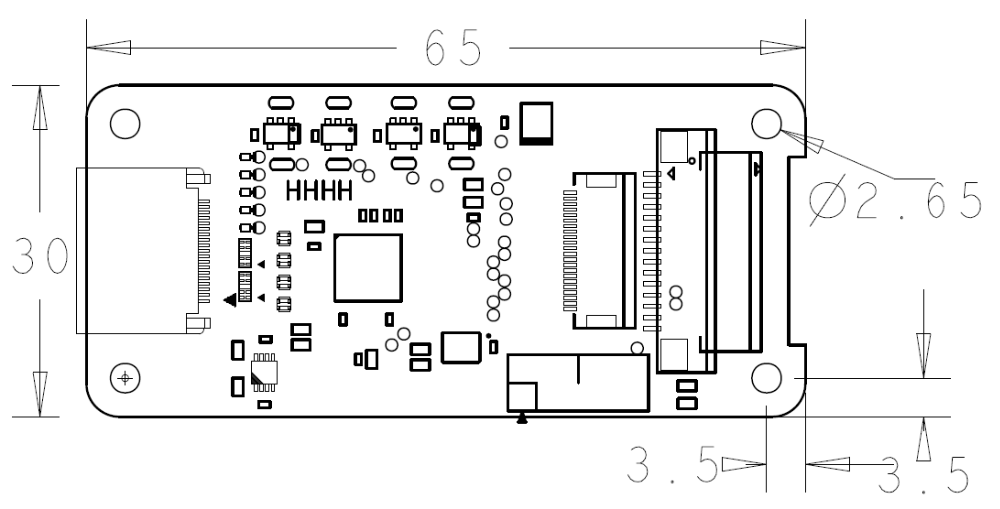 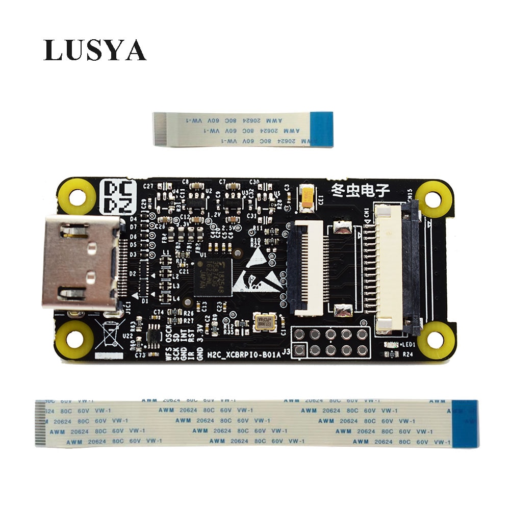 ustreamerpi@pihdmi:~ $ git clone --depth=1 https://github.com/pikvm/ustreamer pi@pihdmi:~ $ cd ustreamer/ pi@pihdmi:~/ustreamer $ make WITH_OMX=1 pi@pihdmi:~/ustreamer $ ./ustreamer --dv-timings --device=/dev/video0 --format=uyvy --encoder=omx \ --workers=3 --persistent --drop-same-frames=30 --host=0.0.0.0 --port=8080 (note, older versions of this board used a baud rate of 9600, so if 115200 doesn't work, try 9600)~ Note: The template provided below did not work on an ESP-01 running Tasmota 8.1.0. It was necessary to manually enter the template in the Configure Template menu. In configuration open Configure Other paste this template and select activate
{"NAME":"LC Technology 4CH Relay","GPIO":[52,255,17,255,255,255,255,255,21,22,23,24,255],"FLAG":0,"BASE":18}
Open Configure Module and set GPIO0, GPIO2, GPIO4 and GPIO5 as Relay1, Relay2, Relay3 and Relay4. Click Save. Enter this command in console (configure the 1st rule) Rule1 on System#Boot do Backlog Baudrate 9600; SerialSend5 0 endon on Power1#State=1 do SerialSend5 A00101A2 endon on Power1#State=0 do SerialSend5 A00100A1 endon on Power2#State=1 do SerialSend5 A00201A3 endon on Power2#State=0 do SerialSend5 A00200A2 endon on Power3#State=1 do SerialSend5 A00301A4 endon on Power3#State=0 do SerialSend5 A00300A3 endon on Power4#State=1 do SerialSend5 A00401A5 endon on Power4#State=0 do SerialSend5 A00400A4 endon Enable the rule (type rule1 1 in the Tasmota console) https://tasmota.github.io/docs/devices/Nedis-WIFIP310FWT/ https://templates.blakadder.com/nedis_WIFIP310FWT.html Description: 3 port AC outlets (European Schucko Type F) + 4 USB power outlets Power input: 16 A - 230 VAC Max. Power: 3680 W Power output: USB: 5 VDC /2.4 A each mapping
Template:
{"NAME":"Nedis WIFIP310","GPIO":[0,56,0,17,22,21,0,0,0,23,24,0,0],"FLAG":1,"BASE":18}
new template for version 9IO":[0,320,0,32,225,224,0,0,0,226,227,0,0,4704],"FLAG":0,"BASE":18} 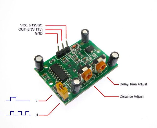 BISS001 moduleBISS001 - Micro Power PIR Motion Detector IC
HC-SR501 moduleTechnical data of the HC-SR501 Motion and Sensor Modules: Input voltage: 4.5 V - 20 V Digital output when motion is detected: 3.3 V (high) Digital output with no movement on the HC-SR501: 0 V (low) Working temperature in the environment: -15 � C to 70 � C Delay Time 0.5 to 200 seconds Angle of coverage: 100 � Reach 5m - 7m Size of the HC-SR501 motion: Sensor Lens diameter: 23mm Length: 24.03mm Width: 32.34mm Height (with lens): 24.66mm Center screw hole spacing: 28 mm Screw hole diameter: 2mm (M2) Collect pir data using Linux gpio and send it to mqttboth pots are all the way to the left (if jumper is on the left toword edge of board) to make minimal timeout pir.shgpio-utilsgpio-utils exists on Raspberry Pi #!/bin/sh -e led=/sys/devices/platform/rpi_control_board/leds/d1/brightness # pir sensor connceted to 5V, GPIO12, GND sudo stdbuf -oL -eL gpio-event-mon -n gpiochip0 -o 12 -r -f | while read gpio event time dir edge ; do case $dir in rising) echo -n "^" echo 1 > $led ;; falling) echo -n "_" echo 0 > $led ;; *) echo -n "?" ;; esac done gpiodalternative version using gpiod package available on sunxi #!/bin/sh -e led=/sys/class/leds/orangepi:red:status/brightness # pir sensor connceted to 5V, PA6, GND sudo stdbuf -oL -eL gpiomon 0 6 | while read event dir edge time ; do echo "# $dir" case $dir in RISING) echo -n "^" echo 1 > $led ;; FALLING) echo -n "_" echo 0 > $led ;; *) echo -n "?" ;; esac done
This page tries to document my experiments using accelerometers ADXL335Board: GY-61.
ADXL335 3-axis Accelerometer
Supply Voltage: 3V - 5V MPU-9250Board: Grove - IMU 10DOF v1.1 https://wiki.seeedstudio.com/Grove-IMU_10DOF/ Grove - IMU 10DOF v1.1.pdf
MPU-9250 addr: 0x68 This board has 5V -> 3V3 level shifter but works with 3V3 as VCC
root@rpi4:~# i2cdetect -y 1
     0  1  2  3  4  5  6  7  8  9  a  b  c  d  e  f
00:          -- -- -- -- -- -- -- -- -- -- -- -- --
10: -- -- -- -- -- -- -- -- -- -- -- -- -- -- -- --
20: -- -- -- -- -- -- -- -- -- -- -- -- -- -- -- --
30: -- -- -- -- -- -- -- -- -- -- -- -- -- -- -- --
40: -- -- -- -- -- -- -- -- -- -- -- -- -- -- -- --
50: -- -- -- -- -- -- -- -- -- -- -- -- -- -- -- --
60: -- -- -- -- -- -- -- -- 68 -- -- -- -- -- -- --
70: -- -- -- -- -- -- -- 77

root@rpi4:~# modprobe configs
root@rpi4:~# zgrep INV /proc/config.gz
CONFIG_INV_MPU6050_IIO=m
CONFIG_INV_MPU6050_I2C=m
# CONFIG_INV_MPU6050_SPI is not set

root@rpi4:~# modprobe inv-mpu6050-i2c

root@rpi4:~# echo mpu9250 0x68 > /sys/class/i2c-adapter/i2c-1/new_device
[Sat Jan  9 14:10:25 2021] inv-mpu6050-i2c 1-0068: mounting matrix not found: using identity...
[Sat Jan  9 14:10:25 2021] inv-mpu6050-i2c 1-0068: 1-0068 supply vddio not found, using dummy regulator
[Sat Jan  9 14:10:25 2021] inv-mpu6050-i2c 1-0068: trigger probe fail -22
[Sat Jan  9 14:10:25 2021] inv-mpu6050-i2c: probe of 1-0068 failed with error -22
[Sat Jan  9 14:10:25 2021] i2c i2c-1: new_device: Instantiated device mpu9250 at 0x68

root@rpi4:~# echo bmp180 0x77 > /sys/class/i2c-adapter/i2c-1/new_device
[Sat Jan  9 14:12:17 2021] i2c i2c-1: new_device: Instantiated device bmp180 at 0x77
[Sat Jan  9 14:12:17 2021] bmp280 1-0077: 1-0077 supply vddd not found, using dummy regulator
[Sat Jan  9 14:12:17 2021] bmp280 1-0077: 1-0077 supply vdda not found, using dummy regulator
[Sat Jan  9 14:12:17 2021] bmp280 1-0077: non-rising trigger given for EOC interrupt, trying to enforce it
[Sat Jan  9 14:12:17 2021] bmp280 1-0077: unable to request DRDY IRQ

root@rpi4:~# iio_info
Library version: 0.16 (git tag: v0.16)
Compiled with backends: local xml ip usb serial
IIO context created with local backend.
Backend version: 0.16 (git tag: v0.16)
Backend description string: Linux rpi4 5.4.79-v7l+ #1373 SMP Mon Nov 23 13:27:40 GMT 2020 armv7l
IIO context has 1 attributes:
	local,kernel: 5.4.79-v7l+
IIO context has 1 devices:
	iio:device0: bmp180
		2 channels found:
			pressure:  (input)
			3 channel-specific attributes found:
				attr  0: input value: 100.646000000
				attr  1: oversampling_ratio value: 8
				attr  2: oversampling_ratio_available value: 1 2 4 8
			temp:  (input)
			3 channel-specific attributes found:
				attr  0: input value: 24800
				attr  1: oversampling_ratio value: 1
				attr  2: oversampling_ratio_available value: 1
Hm. bmp180 works, mpu9250 doesn't It needs full device tree overlay https://github.com/dpavlin/linux-gpio-pinout/blob/master/device-tree/grove-imu10dof.dts WB3-12 360 Degree Microwave Motion Detector Module 12V-35V
Features: In my testing works on 5V, has 10s delay on trigger.
iio.conf
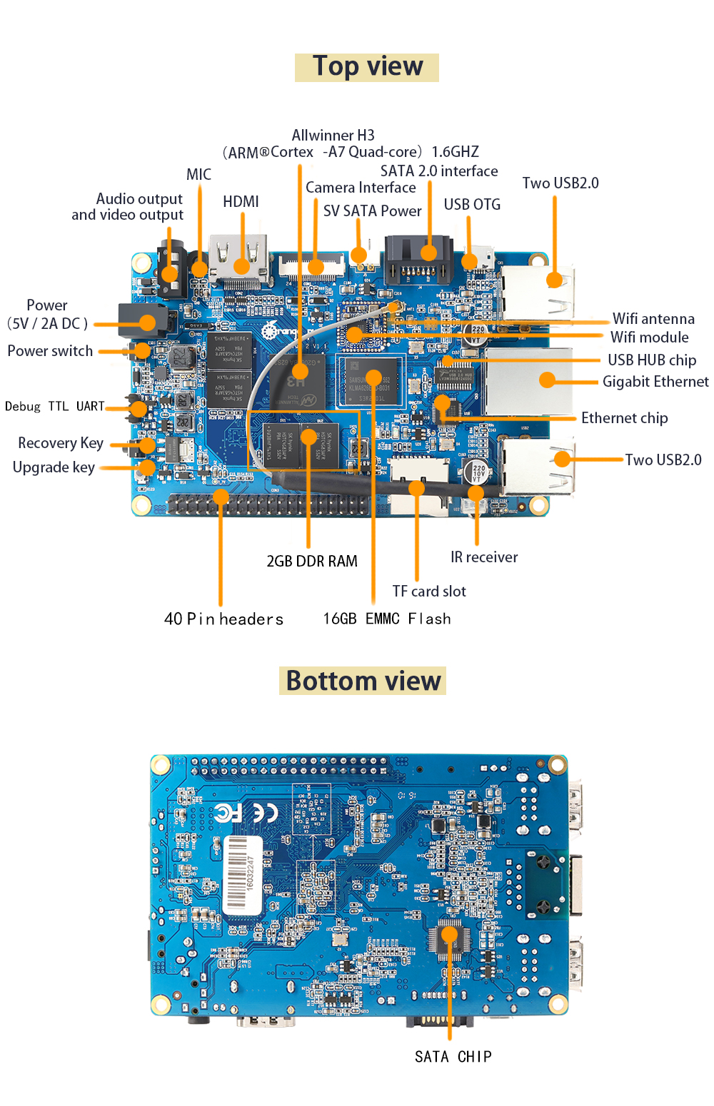 http://www.orangepi.org/orangepiplus2/ https://www.armbian.com/orange-pi-plus-2/
SoC H3 @ 1.2GHz[1] bme280 i2c temperature/humidity/pressure
/home/dpavlin/linux-gpio-pinout/overlay-load.sh /boot/dtb-`uname -r`/overlay/*h3*i2c0*

root@opip:/home/dpavlin/linux-gpio-pinout# i2cdetect -y 2
     0  1  2  3  4  5  6  7  8  9  a  b  c  d  e  f
00:          -- -- -- -- -- -- -- -- -- -- -- -- --
10: -- -- -- -- -- -- -- -- -- -- -- -- -- -- -- --
20: -- -- -- -- -- -- -- -- -- -- -- -- -- -- -- --
30: -- -- -- -- -- -- -- -- -- -- -- -- -- -- -- --
40: -- -- -- -- -- -- -- -- -- -- -- -- -- -- -- --
50: -- -- -- -- -- -- -- -- -- -- -- -- -- -- -- --
60: -- -- -- -- -- -- -- -- -- -- -- -- -- -- -- --
70: -- -- -- -- -- -- 76 --
Check i2c address in datasheet
Connecting SDO to GND results in slave root@opip:/home/dpavlin/linux-gpio-pinout# zgrep BMP280 /proc/config.gz CONFIG_BMP280=m CONFIG_BMP280_I2C=m CONFIG_BMP280_SPI=m root@opip:/home/dpavlin/linux-gpio-pinout# echo bmp280 0x76 > /sys/bus/i2c/devices/i2c-2/new_device root@opip:/home/dpavlin/linux-gpio-pinout# [Sat Jan 2 11:43:58 2021] i2c i2c-2: new_device: Instantiated device bmp280 at 0x76 [Sat Jan 2 11:43:58 2021] bmp280 2-0076: supply vddd not found, using dummy regulator [Sat Jan 2 11:43:58 2021] bmp280 2-0076: supply vdda not found, using dummy regulator [Sat Jan 2 11:43:58 2021] bmp280 2-0076: bad chip id: expected 58 got 60 [Sat Jan 2 11:43:58 2021] bmp280: probe of 2-0076 failed with error -22 So it's not BMP280, but BME280.
Using https://www.raspberrypi-spy.co.uk/2016/07/using-bme280-i2c-temperature-pressure-sensor-in-python/ root@opip:/home/dpavlin# ./bme280.py Chip ID : 96 Version : 0 Temperature : 24.65 C Pressure : 998.4304559219445 hPa Humidity : 41.458674890198445 %e So let's try with correct sensor name root@opip:/sys/bus/i2c/devices/i2c-2# echo bme280 0x76 > /sys/bus/i2c/devices/i2c-2/new_device [Sat Jan 2 12:32:01 2021] bmp280 2-0076: supply vddd not found, using dummy regulator [Sat Jan 2 12:32:01 2021] bmp280 2-0076: supply vdda not found, using dummy regulator [Sat Jan 2 12:32:01 2021] i2c i2c-2: new_device: Instantiated device bme280 at 0x76 root@opip:~# apt install libiio-utils root@opip:~# iio_info Library version: 0.16 (git tag: v0.16) Compiled with backends: local xml ip usb serial IIO context created with local backend. Backend version: 0.16 (git tag: v0.16) Backend description string: Linux opip 5.10.0-rc7-sunxi #20.11.3 SMP Fri Dec 11 21:18:30 CET 2020 armv7l IIO context has 1 attributes: local,kernel: 5.10.0-rc7-sunxi IIO context has 1 devices: iio:device0: bme280 3 channels found: humidityrelative: (input) 2 channel-specific attributes found: attr 0: input value: 40775 attr 1: oversampling_ratio value: 16 pressure: (input) 2 channel-specific attributes found: attr 0: input value: 99.809761718 attr 1: oversampling_ratio value: 16 temp: (input) 2 channel-specific attributes found: attr 0: input value: 25350 attr 1: oversampling_ratio value: 2 collect using telegrafroot@opip:/etc/telegraf/telegraf.d# ../telegraf --config iio.conf --test 2021-01-02T12:39:39Z I! Starting Telegraf > iio,host=opip,name=bme280 humidityrelative=39.934,pressure=99.801214843,temperature=25.66 1609591179000000000
System Information sound[ 4.645562] sof-audio-pci 0000:00:1f.3: hda codecs found, mask 5 [ 4.645563] sof-audio-pci 0000:00:1f.3: using HDA machine driver skl_hda_dsp_generic now [ 4.645566] sof-audio-pci 0000:00:1f.3: DMICs detected in NHLT tables: 2 [ 4.645590] sof-audio-pci 0000:00:1f.3: firmware: failed to load intel/sof/sof-cml.ri (-2) [ 4.645591] sof-audio-pci 0000:00:1f.3: Direct firmware load for intel/sof/sof-cml.ri failed with error -2 [ 4.645593] sof-audio-pci 0000:00:1f.3: error: request firmware intel/sof/sof-cml.ri failed err: -2 [ 4.645593] sof-audio-pci 0000:00:1f.3: error: failed to load DSP firmware -2 firmware is not part of debian yet https://bugs.debian.org/cgi-bin/bugreport.cgi?bug=960788 pcscdpavlin@x1:~$ sudo apt install pcscd pcsc-tools dpavlin@x1:~$ wget https://www.eid.hr/sites/default/files/eidmiddleware_v3.2.0_amd64.deb dpavlin@x1:~$ sudo dpkg -i eidmiddleware_v3.2.0_amd64.deb dpavlin@x1:~$ /usr/lib/akd/eidmiddleware/Client eidOve upute su bazirane na emardovom postu.
Evo za potpisivanje sa osobnim preko linuxa.
Probajte ako neko može to još dobit onda bismo
aktiviraj karticu pomoću pina na sigurnoj omotnici $ /usr/lib/akd/eidmiddleware/Client postavi konfiguraciju za gpgsm i externi pkcs11 driver $ mkdir .gnupg $ cat ~/.gnupg/gpg-agent.conf scdaemon-program /usr/bin/gnupg-pkcs11-scd $ cat ~/.gnupg/gnupg-pkcs11-scd.conf # pin cache period in seconds pin-cache 5 providers eidosobna provider-eidosobna-library /usr/lib/akd/eidmiddleware/pkcs11/libEidPkcs11.so provider-eidosobna-allow-protected-auth check: $ gpg --card-status should list something about card $ echo "SCD LEARN" | gpg-agent --server gpg-connect-agent should show some key info $ gpgsm --import < /usr/lib/akd/eidmiddleware/certificates/AKDCARoot.pem gpgsm: total number processed: 1 gpgsm: imported: 1 $ gpgsm --import < /usr/lib/akd/eidmiddleware/certificates/HRIDCA.pem gpgsm: total number processed: 1 gpgsm: imported: 1 $ gpgsm --learn-card # check: this should list keys learned from the card: $ gpgsm --list-keys Put the fingerprint of your root CA to "~/.gnupg/trustlist.txt". After fingerprint append " S" (space S without quotes) $ cat ~/.gnupg/trustlist.txt # /CN=AKDCA Root/O=AKD d.o.o./C=HR/2.5.4.97=VATHR-99993087891 99:99:A6:C0:7A:1B:20:89:9E:89:6C:A1:A3:AD:D9:65:34:39:94:58 S # use default key ID for signing $ cat ~/.gnupg/gpgsm.conf # use specific key ID for signing (choose key ID from gpgsm --list-keys) default-key 0x1234ABCD # use default key ID for signing $ gpgsm --detach-sign file.txt > file.txt.sgn # use specific key ID for signing (choose key ID from gpgsm --list-keys) $ gpgsm --detach-sign -u 0x1234ABCD file.txt > file.txt.sgn ... dialog to enter card PIN for the chosen key will appear ... # verify the signature $ gpgsm --verify file.txt.sgn file.txt # kill agent after use (eventual pins cached) $ gpgconf --kill gpg-agent firefoxpreferences > privacy & security > certificates > security devices > load /usr/lib/akd/eidmiddleware/pkcs11/libEidPkcs11.so https://github.com/icebreaker-fpga/icebreaker iCE40UP5K interesting ice40 projects: usb analyzer
https://github.com/smunaut/iua usb audio device
part 1: https://youtu.be/4-JE2nZt0sk https://github.com/smunaut/ice40-playground/tree/master/projects/usb_audio |
Weblog Archives
|