links
- http://www.esp8266.com/
- https://github.com/esp8266/esp8266-wiki/wiki
- http://www.electrodragon.com/w/Wi07c
- https://nurdspace.nl/ESP8266
- Documentation, tools, firmwares https://onedrive.live.com/?cid=C4DDF72E6EEA3826&id=C4DDF72E6EEA3826%21631
- https://github.com/esp8266/arduino
- https://github.com/igrr/esptool-ck (with reset support)
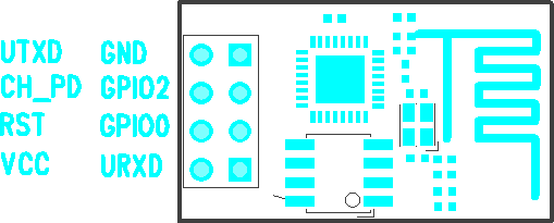
- all IO is 3.3V (3.6V max)
- CH_PD i chip-enable and has to be connected to VCC (3.3V)
- RST, GPIO0, GPIO2 should be pulled up to VCC for normal operation (GPIO0 at minumum!)
- GPIO0 pull to ground for firmware update
- make sure that 3.3V VCC power supply can support 300-400mA or there WILL be problems!
serial port
baud rate 115200
AT+GMR
00160901

OK

AT+RST

OK

 ets Jan  8 2013,rst cause:4, boot mode:(3,7)

wdt reset
load 0x40100000, len 24444, room 16
tail 12
chksum 0xe0
ho 0 tail 12 room 4
load 0x3ffe8000, len 3168, room 12
tail 4
chksum 0x93
load 0x3ffe8c60, len 4956, room 4
tail 8
chksum 0xbd
csum 0xbd

ready
ESP-201
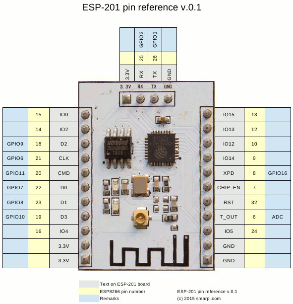
from http://smarpl.com/content/esp8266-esp-201-module-first-impressions
One quirk with the ESP-201 is that is IO15 has to be grounded for the device to function. To flash the device IO00 has to be grounded.
AT+RST

OK

 ets Jan  8 2013,rst cause:4, boot mode:(3,7)

wdt reset
load 0x40100000, len 212, room 16
tail 4
chksum 0x5e
load 0x3ffe8000, len 788, room 4
tail 0
chksum 0x1c
load 0x3ffe8314, len 72, room 8
tail 0
chksum 0x55
csum 0x55
jump to user1
modify flash for dio instead of qio: http://smarpl.com/content/esp8266-esp-201-module-freeing-gpio9-and-gpio10
nodemcu
- https://github.com/nodemcu/nodemcu-firmware
- https://github.com/nodemcu/nodemcu-firmware/wiki/nodemcu_api_en
esptool.py
dpavlin@x200:/rest/cvs/esptool$ git remote -v
origin  https://github.com/themadinventor/esptool (fetch)
origin  https://github.com/themadinventor/esptool (push)

dpavlin@x200:/rest/cvs/esptool$ ./esptool.py --port /dev/ttyUSB2 read_mac
Connecting...
MAC: 18:fe:34:a0:38:72
flash firmware
dpavlin@blue:/opt/Espressif/esptool$ ./esptool.py read_mac
Connecting...
MAC: 18:fe:34:a0:38:72
dpavlin@blue:/opt/Espressif/esptool$ ./esptool.py --port /dev/ttyUSB0 write_flash 0x00000 ../nodemcu-firmware/pre_build/latest/nodemcu_latest.bin
Connecting...
Erasing flash...
Writing at 0x00010800... (17 %)
Get latest build from https://github.com/nodemcu/nodemcu-firmware/releases
dpavlin@x200:/rest/cvs/esptool$ ./esptool.py --port /dev/ttyUSB2 write_flash 0x00000 ./nodemcu_float_0.9.6-dev_20150406.bin

dpavlin@x200:/rest/cvs/esptool$ microcom -p /dev/ttyUSB2 -s 9600
connected to /dev/ttyUSB2
Escape character: Ctrl-\
Type the escape character followed by c to get to the menu or q to quit

> node.restart()

NodeMCU 0.9.6 build 20150406  powered by Lua 5.1.4
lua: cannot open init.lua
>
build from source
For latest features, you might want to rebuild software from github source
dpavlin@x200:/rest/cvs$ git clone https://github.com/pfalcon/esp-open-sdk.git

dpavlin@x200:/rest/cvs/esp-open-sdk$ export PATH=/rest/cvs/esp-open-sdk/xtensa-lx106-elf/bin:$PATH


git clone https://github.com/nodemcu/nodemcu-firmware.git
cd nodemcu-firmware

dpavlin@x200:/rest/cvs/nodemcu-firmware$ git checkout -b dev origin/dev
Branch dev set up to track remote branch dev from origin.
Switched to a new branch 'dev'


make

# check that device is in boot loader mode

dpavlin@x200:/rest/cvs/nodemcu-firmware$ ../esptool/esptool.py --port /dev/ttyUSB1 read_mac
Connecting...
MAC: 18:fe:34:99:f2:83

# flash new firmware

dpavlin@x200:/rest/cvs/nodemcu-firmware$ make flash ESPPORT=/dev/ttyUSB1
make -C ./app flash
make[1]: Entering directory '/rest/cvs/nodemcu-firmware/app'
../tools/esptool.py --port /dev/ttyUSB1 write_flash 0x00000 ../bin/0x00000.bin 0x10000 ../bin/0x10000.bin
Connecting...
Erasing flash...
Writing at 0x0000c500... (100 %)
Erasing flash...
Writing at 0x00068c00... (100 %)

Leaving...
make[1]: Leaving directory '/rest/cvs/nodemcu-firmware/app'
A library for the Microchip MCP3021 A/D converter for use with the ESP8266.
https://github.com/AllAboutEE/ESP8266-MCP3021-Library
nodemcu-uploader
dpavlin@x200:/rest/cvs$ git clone https://github.com/kmpm/nodemcu-uploader
dpavlin@x200:/rest/cvs/nodemcu-uploader$ ./nodemcu-uploader.py --port /dev/ttyUSB2 --baud 9600 file list
Listing files
for key,value in pairs(file.list()) do print(key,value) end
>
OpenOCD JTAG
https://github.com/projectgus/openocd
http://www.esp8266.com/viewtopic.php?f=9&t=1871#p11157
JTAG Signal -> ESP8266 GPIO Pin -> JTAG Pin (standard 20 pin connector)
TMS -> 14 -> 7
TDI -> 12 -> 5
TCK -> 13 -> 9
TDO -> 15 -> 13
RST -> RST -> 15
ESP8266 as wireless JTAG Programmer
https://github.com/emard/wifi_jtag
WIFI
software serial
- C library https://github.com/plieningerweb/esp8266-software-uart
- Arduino https://github.com/plerup/espsoftwareserial
Sonoff
https://www.itead.cc/sonoff-wifi-wireless-switch.html
http://wiki.iteadstudio.com/Sonoff
https://github.com/arendst/Sonoff-MQTT-OTA
pinout
My sonoff is early model, with just 4 pins (instead of 5)
1 - VCC
2 - RX
3 - TX
4 - GND
Programming
use dio not qio to fix checksum errors
CH340 USB to ESP8266 ESP-01 Wifi Module Adapter
It doesn't have GPIO0 connected to ground, so flashing doesn't work!
http://www.esp8266.com/wiki/doku.php?id=all-in-one-esp-usb-converter
ESP-01S DHT11 board
#define DHTTYPE DHT11
#define DHTPIN  2
DHT dht(DHTPIN, DHTTYPE, 11);
adding IR led
Button is connected to RST, and if you want to add IR led (with transistor and resistor) it seems that only
way to make it work is to connect it to RX pin (gpio3). For more info see my blog post: https://blog.rot13.org/2019/08/emulate-ir-remote-for-tv-or-hvac-from-command-line-using-tasmota.html